Friday, April 26, 2013

TouchDesigner | Sculpture

In the ever growing list of tools that I'm experimenting with Derivative's TouchDesigner is a tool that time and again keeps coming up as something that's worth learning, experimenting with, and developing competencies around it's work flow. TD is a nodal environmental called a network. Inside of the network nodes can be directly connected by by exporting parameters. 

Nodes, also called Ops (Operations) are split into families specific to the characteristics of their behavior: CHOPS (Channel Operators), TOPS (Texture Operators), SOPS (Surface Operators), MATS (Materials), and DATS (Data Operators). Nodes from within the same families can pass data directly to one another through patch cords (similar to MaxMSP and Isadora). The output of nearly every node can be passed into other nodes by exporting parameter values. This process divides the process of passing data values into two distinct processes, one that's centered around like to like processes and one that's about moving from like to different. 

TouchDesigner's nodes are the most powerful when they're connected. Like Max single nodes do little by themselves, and are the most powerful when they're connected. Also like Max the flexibility of TD is it's ability to build nearly anything, and with that comes the fact that little is already built. Similar to Isadora is the native ability to build user interfaces as a part of the very fabric of building a program / user experience. 
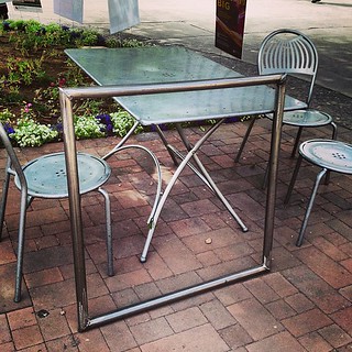
One of the projects that I'm working on this semester is for a sculpture course. This course, called New Systems, is intended to address the link between media and sculpture. One of the areas that I'm interested in exploring is about collecting data from a circus apparatus and using that to drive a visualization in performance. I'm most interested in the direct link between how an apparatus is behaving and how that data can be interpreted in other ways. To that end this semester I set to the work of building an apparatus and determining how to parse that data. In my case I decided to use this opportunity to experiment with TouchDesigner as a means of driving the media. While I was successful in welding together a square from stainless steel, after some consultation from my peers in my sculpture course it was determined that this structure was probably not safe to perform on. Originally I had planned to use a contact mic to capture some data from my interaction with the apparatus, and after a little bit of thinking and consultation with my adviser (Jake Pinholster) I decided that gyroscope data might be more useful.

My current plan is to move away from this being a performance apparatus and instead think of it as installed sculptural piece that serves as a projection surface. For data I'll be using an iPod Touch running Hexler's touch OSC. Touch OSC passes data using UDP packets to communicate over a wired or wireless network using Open Sound Control (OSC). One of the many things that Touch OSC can do is pass the accelerometer data from an iOS device out to other applications. In my case Touch OSC is passing this information to TouchDesigner. TD is then used to pull this information and drive some of the media.
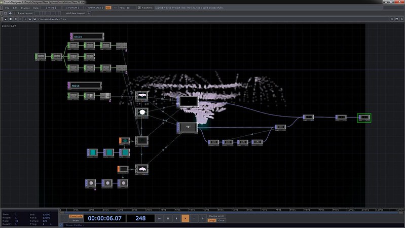


One of the challenges that my adviser posed in this process was to create three scenes that the  media moved through. For the sake of experimentation I applied this challenge to the idea of working with containers in TouchDesigner. Containers are a method of encapsulation in TD, they're a generic kind of object that can hold just about any kind of system. In my case I have three containers that are equivalent to different scenes. The time line moves the viewer through the different containers by cross-fading between them. Each container holds it's own 3D environment that's rendered in real time and linked to the live OSC inputs coming from an iPod touch. 

The best way to detail the process of programming this installation is to divide it up into the component pieces that make it all work. The structure of this network is defined by three hierarchical levels: The Container, Control, and Final Output; the individual composited scene, the underlying geometry.


Want to work your way through these ideas one chunk at a time? Visit their individual Posts here:
The Underlying Geometry
The Individual Composited Scene
The Container, Control, and Final Ouput

Want to work you way through the whole process, keep on scrolling.


The Underlying Geometry

One of the benefits of working with TouchDesigner is the ability to work in 3D. 3D objects are in the family of operators called SOPs - Surface Operators. One of the aesthetic directions that I wanted to explore was the feeling of looking into a long box. The world inside of this box would be characterized by examining artifacts as either particles or waves with a vaguely dual-slit kind of suggestion. With that as a starting point I headed into making the container for these worlds of particles and waves.
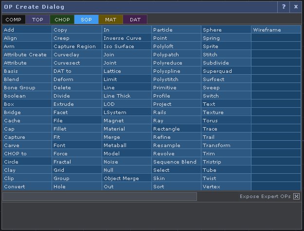


Before making any 3D content it's important to know how TouchDesigner processes these objects in order to display them. On their own, Surface Operators can't be displayed as a rendered texture. In TouchDesigner's idiom textures are two-dimension surfaces, and it follows that the objects that live in that category are called TOPs, Texture Operators. Operators from different families can't be directly connected with patch chords. In order to pass the information from a SOP to a TOP one must use a TOP called a Render. The Render TOP must be connected to three COMPs (Compositions) in order to create an image that can be displayed. The render TOP requires a Geometry COMP (something to be rendered), a Light COMP (something to illuminate the scene), and a Camera COMP (the perspective from which the object is to rendered). In this respect TD pulls from conventions familiar to anyone who has worked with Adobe's After Effects. 

Knowing the component pieces required in order to successfully render a 3D object it's easier to understand how I started to create the underlying geometry. The Geometry COMP is essentially a container object (with some special attributes) that holds the SOPs responsible for passing a surface to the Render TOP. The default Geometry COMP contains a torus as a geometry. 


We can learn a little about how the COMP is working by taking a look inside of the Geometry object. 


Here the things to pay close attention to are the two flags on the torus object. You'll notice in the bottom right corner there is a purple and a blue circle that are illuminated. The purple circle is a "Render Flag" and tells TouchDesigner to render the object, and the blue circle is a "Display Flag" which tells TouchDesigner that this is the object that should be displayed in the Geometry COMP.

Let's take a look at the network that I created.


Now let's dissect how my geometry network is actually working. At first glance we can see that multiple objects are being combined into a single piece of geometry that's ultimately being passed out of this Geometry COMP. 



If we look closer we'll see that here that the SOP network looks like this:
Grid - Noise - Transform - Alpha Noise (here the bypass flag is turned on)
Grid creates a plane that's created out of polygons. This is different from a rectangle that's only composed four points. In order to create a surface that can deform I needed a SOP points in the middle of it. The grid is attached to a Noise SOP that's animating the surface. Noise is attached to a transform SOP that allows me to change the position of this individual plane. The last stop in this chain is another Noise SOP. Originally I was experimenting with varying the transparency of the surface. Ultimately, I decided to move away from this look. Rather than cutting this out of the chain, I simply turned on the Bypass Flag which turns off this single SOP. This whole chain is repeated eight times (for a total of eight grids). 
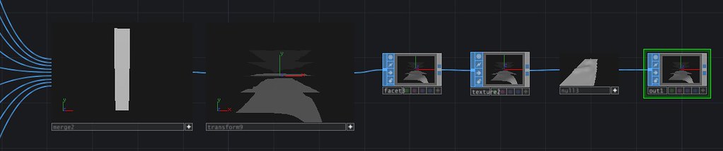

These Nine planes are then connected so that the rest of the network looks like this:
Merge - Transform - Facet - Texture - Null - Out
Merge takes all of the inputs and puts them together into a single piece of geometry. Transform allows me to move object as a whole in space. Facet is a handy operator that allows you to compute the normals' of a geometry, which is useful for creating some more dynamic shading. Texture was useful for another direction that I was exploring, ultimately  ended up turning on the bypass flag for this SOP. A null, like in other environments, is really just a place holder kind of object. In the idiomatic structure of TouchDesigner, the Null is operationally an object that one places at the end of operation string. This is considered a best practice for a number of reasons. High on the list of reasons to end a string in a Null is because this allows easy access for making changes to a string. TouchDesigner allows the programmer to insert operations between objects. By always ending a string in a Null it becomes very easy to make changes to the stream without having to worry about re-exporting parameters. Finally all of this ends in an Out. While the Out isn't necessary for this string, at one point I wasn't sure if I was going to pass this geometry into another component. Ending in the Out ensured that I would have that flexibility if I needed it.


The Individual Composited Scene

There are always large questions to answer when thinking about creating an interactive work: Who is it for? What does it look likes? What are you trying to communicate? How much instruction do you provide, how little instruction do you provide? And on and on.  As I started to think about how this piece was going to work as an installation rather than as a performance apparatus, I started by thinking about what kind of data I could use to drive the visual elements of this work. One of the sensors that I knew I could easily incorporate into my current sculptural configuration was a an iPod Touch. The Touch has an on-board gyroscope and accelerometer. After a conversation with my adviser (Jake Pinholster) we decided that this would be a direction of exploration worth pulling apart, and from there I went back to TouchDesigner to start thinking about how I wanted to incorporate live data into the piece I was making.


When dealing with a challenge like building an interactive sculptural system that has at least three different visualizations, it can be challenging to think about where to start. Different programmers are bound to have different approaches to addressing this question. My approach was to start by thinking about what kind of input data I had to work with. Because I was dealing with a sensor that relayed spatial information, this also help me think about how to represent that data. Next I thought about what different kinds of ways I wanted to present this information, and finally I addressed how to playback this experience for users. Some of my more esoteric and existential questions (why am I making this? what does it mean? what does it represent?) were addressed through the methodical programming process, and others were sussed out over contemplative cups of coffee. As much as I wish that these projects could have a straight line of execution, a checklist even, I'm discovering more and more that the act of creating and programming is often a winding path with happy (and unhappy) discoveries along the way.

My first step on this journey, however, was to address what kind of inputs I had to use. Hexler has an excellent app for sending UDP messages over wireless connections called Touch OSC. OSC, or Open Sound Control, is a communications protocol that uses UDP messages to send data over wired and wireless networks. It's functionally similar to MIDI and has some additional flexibilities and constraints. In the case of touch OSC, one of the parameters that you can enable from your iOS device to send xyz data from the accelerometer. Getting Touch OSC up and running does require a few steps to get the ball rolling. First both the computer that's receiving and the device that's broadcasting need to be on the same network. Your broadcasting device will need the IP address of the receiving computer, and a specified port to send the data to (how to find your IP address on a Mac, and on a PC). Once this information is set on your broadcasting device, it's time to add a Channel Operator to your TouchDesigner network.
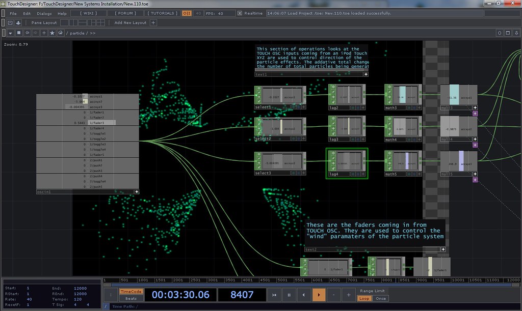


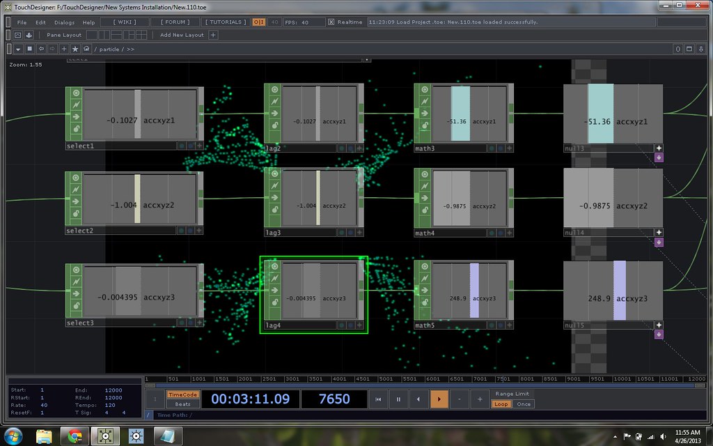
In TouchDesigner, there is a CHOP called "OSC in." This CHOP will allow you to receive OSC data over a wireless network. Once you've added the CHOP to your TD network you'll have to specify the port that Touch OSC is broadcasting to, and then you should be in business. In my case once this was set up I could instantly see a stream of accelerometer data coming from my iPod Touch. In order to use these values, however, I needed to take some additional steps. The raw OSC data from Touch OSC comes in as a range of data from -1 to 1. Additionally, the data comes in from one CHOP. My flow of operators looks like:
OSC In - Select - Lag - Math - Null
OSC In is the data input. The CHOP Select allows you to select a single channel out of a bundle of channels. In this case I used this to separate my X, Y, and Z inputs into different streams. The Lag chop helps to smooth out the attack and decay rates of input data. In my case this ensured that my final values used to control another object where kept from being too jittery. The Math CHOP is tremendously powerful, in my case I wanted to be able to map the values of my raw data [ -1 to 1 ], to a larger range of values, say 0 to 200. Finally I ended my string in a Null. A null in this case is very useful in case I need to add any other operators into my string.


Before thinking about how to use these values, it's important to take a moment to revisit how geometry is rendered in TouchDesigner. The geometry COMPs that are used to create the objects to be displayed can't be visualized without using a render TOP. The render TOP requires three components in order to generate an image that can be seen. Render requires a source geometry, light, and camera. The Geometry COMP provides the location of surfaces, the light provides the necessary information about how the object is being lit. The camera COMP controls the perspective that the object is being rendered from. This is similar to an approach that one might use when creating 3D content in After Effects - an object to be rendered, a light so the object can be seen, and a camera to control the perspective the audience sees of the object. Because we need to think of rendering by combining multiple COMPs, that can inform how we use live data. 
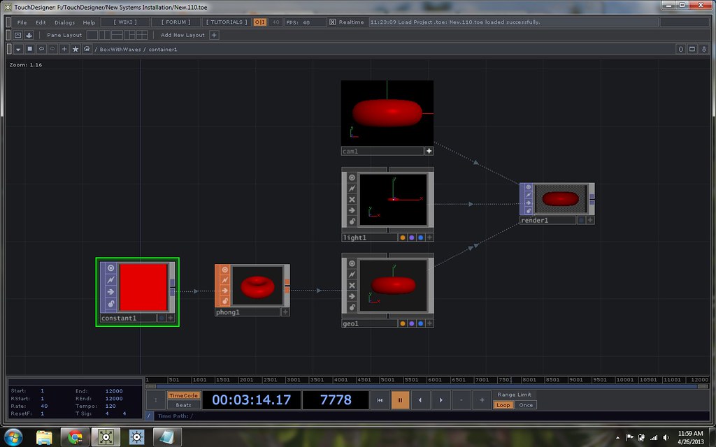


With some scaled values process and ready to export I was ready to think about how these values could influence the viewers perspective of the geometry. One of my initial thoughts was to render a cube that a user could look inside of. As the observer changed the orientation of the sensor, the virtual environment would also change in kind. While it's possible to do this by rotating and translating the geometry itself, I instead decided to focus on the orientation of the camera instead. This has a few advantages. One important advantage is the ability to tell a camera to look directly at a specified geometry. This means that in translating the camera (left or right, up or down, in or out) the camera stays focused on the center of the target geometry. This makes changing perspective much simpler.  


Initially I was thinking of rendering the entire 3D scene as a single geometry. In doing this, however, I was experiencing some challenges when thinking about the placement of lights and the overall organization of the geometry, and in applying texture to the surfaces. By using a Phong shader one can apply texture maps to the 3D geometry COMPs that have been created. By separating the interior and exterior pieces of the geometry and then compositing them after rendering I was able to apply different shaders to each geometry.
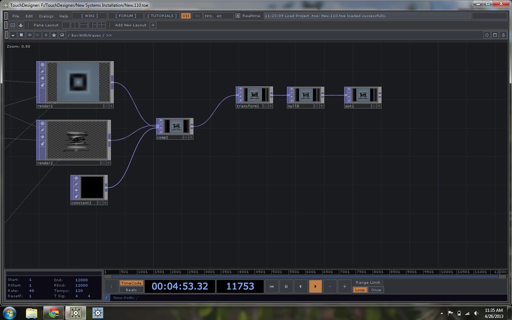


The portion of my network responsible for compositing the geometry looks like this:
Render 1, Render 2, Constant (black solid) - Composit - Transform - Null - Out
 Render 1, Render 2, and the Constant are the three source surfaces. Render 1 is the box, Render 2 is the merged set of waves, and the Constant is a black background. Another approach to this would be to set one of the camera background's as black. These three flow into a Composit COMP. Next is the Transition COMP (this allowed for some small adjustments that needed to be made in order to help align the projection with the sculpture. Originally I made this string with a Null as the final output of this Component. I would eventually find that I needed an Out to pass this scene into another display module. 

I used the same techniques as above for the other two scenes - starting with establishing my data stream, generating the geometry, rendering out layers to be composited and then passed out to the visual stream.

Are these pictures too small? You can see higher quality versions by looking at this Flickr Gallery: Graduate School Documentation


The Container, Control, and Final Output

In thinking about how to meet the objectives that I had for this piece, one of my central questions was how to make sure that I could move through three cued scenes - either with manual or automatic triggers. I knew that I had three different aesthetic environments that I wanted to move through. I explored several different options, and the one that ultimately made sense to me given my current level of proficiency (at this point I had only been programming in Touch for a total of three weeks) in TouchDesigner was to use a cross fading approach. Here's what the whole network looks like:
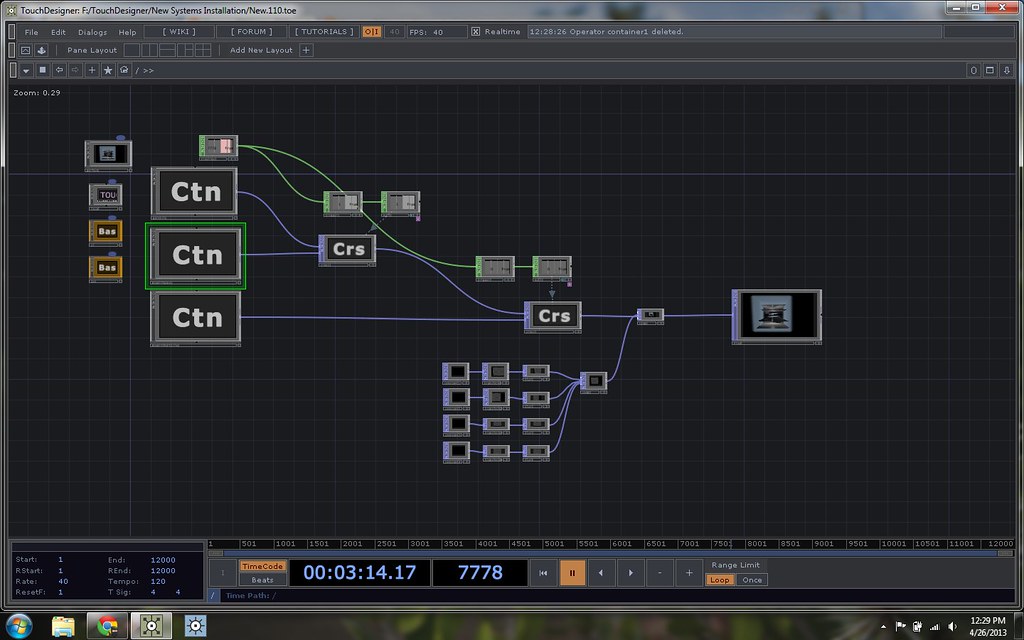


In thinking about how to ensure that I was being efficient I decided to encapsulate my three different scenes in their own respective containers. You'll notice on the left hand side that there are three containers - each holding it's own 3D environment. These are joined through Corss fading TOPs though a final composite (for a mask) until ending in a Null that was used as the display canvas. 

I spent a lot of time thinking about how this piece was going to be both interactive and autonomous. It needed to be interactive in that the user was able to see how their interaction with an object was driving the visual media; it needed to be autonomous in its ability to transition between scenes and then loop back to the beginning of the network. I don't think I've totally cracked the nut that is the right balance of interactivity and self-directed programming, but it feels like I did make strides towards addressing this question. My solution to these issues was to allow the interaction with the projection to be centered around the control of perspective, but to drive the transitions through the scenes with time-line triggers.

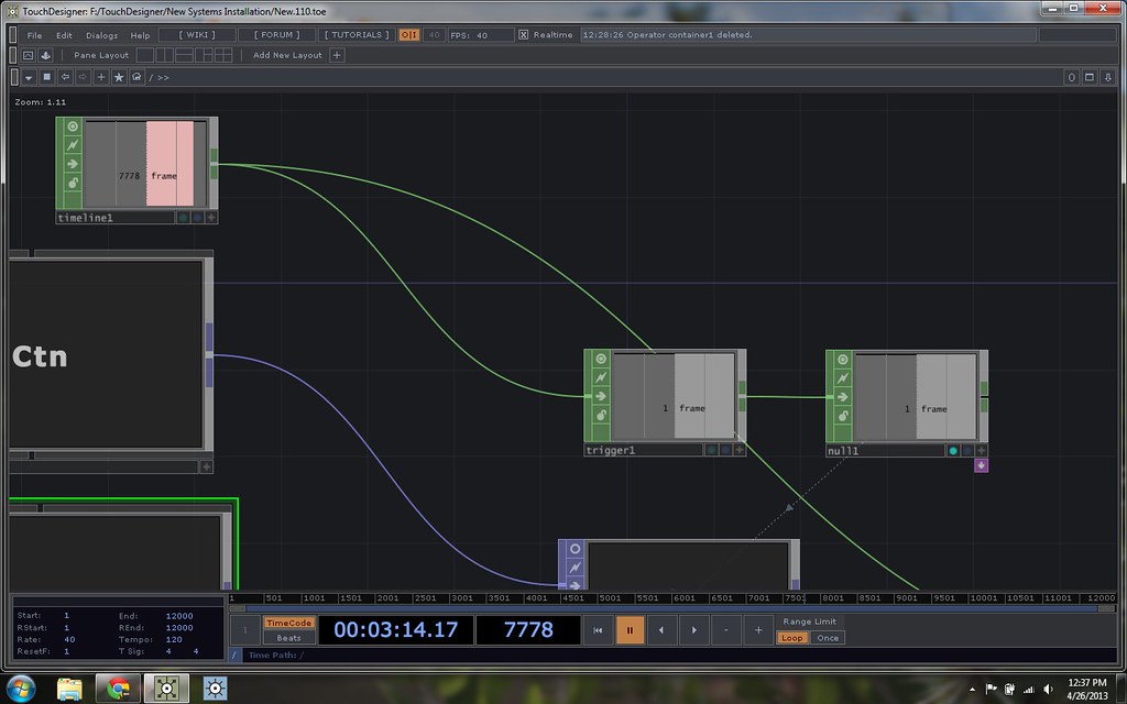
Unlike some other interactive programming environments, TouchDesigner has a timeline built into the fabric of the control system. The Timeline is based in frames, and the programmer can specify the number of frames per second as well as the total number of frames for a given project. My Timeline triggering system was the following string of CHOPs:
Timeline - Trigger - Null
Timeline reports out the current frame number. The trigger CHOP can be set to trigger at a given threshold (or in my case a frame number). This in turn is passed to a null and exported to a Corssfade TOP as a rate for crossfade. The Crossfades are daisy-chained together before finally being attached to the null that's output to the projector.


With the system working I also needed to make a mask for the final projection to ensure that I wasn't displaying any empty grid onto the floor of the gallery where this was being installed. I would typically make a mask for something like this in Photoshop, but decided to try making this all in the TouchDesigner programming environment. My TOP operator string for this looked like:
Contsant - Transform - Blur - Composite
I started by creating a black constant that's then passed to a transform so that it can be positioned into place. This is then passed to a blur to soften the edges, and finally to a composite to create a mask that contains a left, right, top, and bottom side. In hindsight I realize that I could use a single constant passed to four transform TOPs, to be a little more tidy. The mask as a composited object is then composited with final render stream before being passed to the Null that's connected to the projector. 


In the end I'm fairly happy with this project. t's been a steep learning curve, but well worth the hassle, angst, and late nights. It's no small thing to have made a piece of interactive media driven sculpture in a programming environment where that's totally new to me. For as hard as all of this work has proven to be, I have to remind myself that I'm actively doing the work that I came to Graduate School to do. Everyday I realize that I've been changed by my time in the desert, and by my time with the gifted and brilliant artists and friends that I've found here. 


Are these pictures too small? You can see larger versions of them here:

TouchDesigner | The Container, Control, and Final Ouput

In thinking about how to meet the objectives that I had for this piece, one of my central questions was how to make sure that I could move through three cued scenes - either with manual or automatic triggers. I knew that I had three different aesthetic environments that I wanted to move through. I explored several different options, and the one that ultimately made sense to me given my current level of proficiency (at this point I had only been programming in Touch for a total of three weeks) in TouchDesigner was to use a cross fading approach. Here's what the whole network looks like:


In thinking about how to ensure that I was being efficient I decided to encapsulate my three different scenes in their own respective containers. You'll notice on the left hand side that there are three containers - each holding it's own 3D environment. These are joined through Corss fading TOPs though a final composite (for a mask) until ending in a Null that was used as the display canvas. 

I spent a lot of time thinking about how this piece was going to be both interactive and autonomous. It needed to be interactive in that the user was able to see how their interaction with an object was driving the visual media; it needed to be autonomous in its ability to transition between scenes and then loop back to the beginning of the network. I don't think I've totally cracked the nut that is the right balance of interactivity and self-directed programming, but it feels like I did make strides towards addressing this question. My solution to these issues was to allow the interaction with the projection to be centered around the control of perspective, but to drive the transitions through the scenes with time-line triggers.

Unlike some other interactive programming environments, TouchDesigner has a timeline built into the fabric of the control system. The Timeline is based in frames, and the programmer can specify the number of frames per second as well as the total number of frames for a given project. My Timeline triggering system was the following string of CHOPs:
Timeline - Trigger - Null
Timeline reports out the current frame number. The trigger CHOP can be set to trigger at a given threshold (or in my case a frame number). This in turn is passed to a null and exported to a Corssfade TOP as a rate for crossfade. The Crossfades are daisy-chained together before finally being attached to the null that's output to the projector.


With the system working I also needed to make a mask for the final projection to ensure that I wasn't displaying any empty grid onto the floor of the gallery where this was being installed. I would typically make a mask for something like this in Photoshop, but decided to try making this all in the TouchDesigner programming environment. My TOP operator string for this looked like:
Contsant - Transform - Blur - Composite
I started by creating a black constant that's then passed to a transform so that it can be positioned into place. This is then passed to a blur to soften the edges, and finally to a composite to create a mask that contains a left, right, top, and bottom side. In hindsight I realize that I could use a single constant passed to four transform TOPs, to be a little more tidy. The mask as a composited object is then composited with final render stream before being passed to the Null that's connected to the projector. 


In the end I'm fairly happy with this project. t's been a steep learning curve, but well worth the hassle, angst, and late nights. It's no small thing to have made a piece of interactive media driven sculpture in a programming environment where that's totally new to me. For as hard as all of this work has proven to be, I have to remind myself that I'm actively doing the work that I came to Graduate School to do. Everyday I realize that I've been changed by my time in the desert, and by my time with the gifted and brilliant artists and friends that I've found here. 


Are these pictures too small? You can see larger versions of them here:

TouchDesigner | The Individual Composited Scene

There are always large questions to answer when thinking about creating an interactive work: Who is it for? What does it look likes? What are you trying to communicate? How much instruction do you provide, how little instruction do you provide? And on and on.  As I started to think about how this piece was going to work as an installation rather than as a performance apparatus, I started by thinking about what kind of data I could use to drive the visual elements of this work. One of the sensors that I knew I could easily incorporate into my current sculptural configuration was a an iPod Touch. The Touch has an on-board gyroscope and accelerometer. After a conversation with my adviser (Jake Pinholster) we decided that this would be a direction of exploration worth pulling apart, and from there I went back to TouchDesigner to start thinking about how I wanted to incorporate live data into the piece I was making.


When dealing with a challenge like building an interactive sculptural system that has at least three different visualizations, it can be challenging to think about where to start. Different programmers are bound to have different approaches to addressing this question. My approach was to start by thinking about what kind of input data I had to work with. Because I was dealing with a sensor that relayed spatial information, this also help me think about how to represent that data. Next I thought about what different kinds of ways I wanted to present this information, and finally I addressed how to playback this experience for users. Some of my more esoteric and existential questions (why am I making this? what does it mean? what does it represent?) were addressed through the methodical programming process, and others were sussed out over contemplative cups of coffee. As much as I wish that these projects could have a straight line of execution, a checklist even, I'm discovering more and more that the act of creating and programming is often a winding path with happy (and unhappy) discoveries along the way.

My first step on this journey, however, was to address what kind of inputs I had to use. Hexler has an excellent app for sending UDP messages over wireless connections called Touch OSC. OSC, or Open Sound Control, is a communications protocol that uses UDP messages to send data over wired and wireless networks. It's functionally similar to MIDI and has some additional flexibilities and constraints. In the case of touch OSC, one of the parameters that you can enable from your iOS device to send xyz data from the accelerometer. Getting Touch OSC up and running does require a few steps to get the ball rolling. First both the computer that's receiving and the device that's broadcasting need to be on the same network. Your broadcasting device will need the IP address of the receiving computer, and a specified port to send the data to (how to find your IP address on a Mac, and on a PC). Once this information is set on your broadcasting device, it's time to add a Channel Operator to your TouchDesigner network.


In TouchDesigner, there is a CHOP called "OSC in." This CHOP will allow you to receive OSC data over a wireless network. Once you've added the CHOP to your TD network you'll have to specify the port that Touch OSC is broadcasting to, and then you should be in business. In my case once this was set up I could instantly see a stream of accelerometer data coming from my iPod Touch. In order to use these values, however, I needed to take some additional steps. The raw OSC data from Touch OSC comes in as a range of data from -1 to 1. Additionally, the data comes in from one CHOP. My flow of operators looks like:
OSC In - Select - Lag - Math - Null
OSC In is the data input. The CHOP Select allows you to select a single channel out of a bundle of channels. In this case I used this to separate my X, Y, and Z inputs into different streams. The Lag chop helps to smooth out the attack and decay rates of input data. In my case this ensured that my final values used to control another object where kept from being too jittery. The Math CHOP is tremendously powerful, in my case I wanted to be able to map the values of my raw data [ -1 to 1 ], to a larger range of values, say 0 to 200. Finally I ended my string in a Null. A null in this case is very useful in case I need to add any other operators into my string.


Before thinking about how to use these values, it's important to take a moment to revisit how geometry is rendered in TouchDesigner. The geometry COMPs that are used to create the objects to be displayed can't be visualized without using a render TOP. The render TOP requires three components in order to generate an image that can be seen. Render requires a source geometry, light, and camera. The Geometry COMP provides the location of surfaces, the light provides the necessary information about how the object is being lit. The camera COMP controls the perspective that the object is being rendered from. This is similar to an approach that one might use when creating 3D content in After Effects - an object to be rendered, a light so the object can be seen, and a camera to control the perspective the audience sees of the object. Because we need to think of rendering by combining multiple COMPs, that can inform how we use live data. 


With some scaled values process and ready to export I was ready to think about how these values could influence the viewers perspective of the geometry. One of my initial thoughts was to render a cube that a user could look inside of. As the observer changed the orientation of the sensor, the virtual environment would also change in kind. While it's possible to do this by rotating and translating the geometry itself, I instead decided to focus on the orientation of the camera instead. This has a few advantages. One important advantage is the ability to tell a camera to look directly at a specified geometry. This means that in translating the camera (left or right, up or down, in or out) the camera stays focused on the center of the target geometry. This makes changing perspective much simpler.  


Initially I was thinking of rendering the entire 3D scene as a single geometry. In doing this, however, I was experiencing some challenges when thinking about the placement of lights and the overall organization of the geometry, and in applying texture to the surfaces. By using a Phong shader one can apply texture maps to the 3D geometry COMPs that have been created. By separating the interior and exterior pieces of the geometry and then compositing them after rendering I was able to apply different shaders to each geometry.


The portion of my network responsible for compositing the geometry looks like this:
Render 1, Render 2, Constant (black solid) - Composit - Transform - Null - Out
 Render 1, Render 2, and the Constant are the three source surfaces. Render 1 is the box, Render 2 is the merged set of waves, and the Constant is a black background. Another approach to this would be to set one of the camera background's as black. These three flow into a Composit COMP. Next is the Transition COMP (this allowed for some small adjustments that needed to be made in order to help align the projection with the sculpture. Originally I made this string with a Null as the final output of this Component. I would eventually find that I needed an Out to pass this scene into another display module. 

I used the same techniques as above for the other two scenes - starting with establishing my data stream, generating the geometry, rendering out layers to be composited and then passed out to the visual stream.

Are these pictures too small? You can see higher quality versions by looking at this Flickr Gallery: Graduate School Documentation

Wednesday, April 24, 2013

Soot and Spit | Particles in Isadora

Holy challenges Batman. It seems like I'm constantly being humbled by the learning curve of graduate school. This spring one of ASU's productions is Charles Mee's Soot and Spit


Soot and Spit is grounded in the work of James Castle, an artist who was deaf and possibly autistic. One of the most powerful outlets for expression in Castle's life was making art. He made countless works over the course of his life, and one of the mediums that he used was a mixture of soot and spit. With this as a contextual anchor the lead designer, Boyd Branch, was interested in exploring the possibility of using particles as a part of his final design. 

One of my charges in working on this production was to explore how to work with particles in Isadora (our planned play-back system). I started this process by doing a little digging on the web for examples, and the most useful resource that I found as a starting point was the Mark Coniglio (Isadora's creator) example file. Here Mark has a very helpful breakdown of several different kinds of typical operations in Isadora, including a particle system. Looking at the Particle System Actor can feel a little daunting. In my case, The typical approach of toggling and noodling with values to look for changes wasn't really producing any valuable results. It wasn't until I took a close look at Mark's example patch that I was able to finally make some head way.

We can start by looking at the 3D particle actor and working through a few important considerations to keep in mind when working with 3D particles in Isadora. One thing to remember is that when you're creating particles, the rendering system needs multiple attributes for each particle that you're generating (location in x, y, and z, velocity, scale, rotation, orientation, color, lifespan, and so on). To borrow a idiomatic convention from MaxMSP, you have to bang on these attributes for every particle that you create. There are a variety of methods for generating your bang, but for the sake of seeing some consistent particle generation I started by using a pulse generator. Pulse generators in Isadora are expressed in hertz (cycles per second), and when we're working with our particle system we'll frequently want a pulse generator to be attached at the front end of our triggers. To that end, we really want a single pulse generator to be driving as much of our particle generation as possible. This is to ensure all of our data about particle generation is synchronized, and to keep our system over head as low as possible. 

Let's get this party started by making some conceptual plans about how we want to experiment with particles. I started by thinking of the particles as being emitted from a single source and being affected by gravity in a typical manner, i.e. falling towards the ground. 

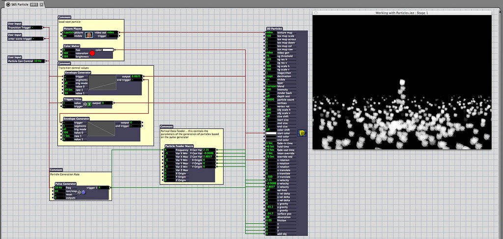
Here's my basic particle emitter set-up for this kind of setup:


Let's start by taking a look at the things we need to get started. As I mentioned before we need to start by frist getting a pulse generator set-up. Let's start by adding a pulse generator, and looking at where it's connected:


Here we can see that the pulse generator is hooked up to a custom user actor that I've called "Particle Feeder," and to the "Add Obj" attribute in the 3D particle Actor. This approach is making sure that we're only using a single pulse generator to bang on our particle system - pushing attribute changes and add object changes.

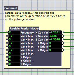
Next let's look at the Particle Feeder actor that I made to make this process easier:


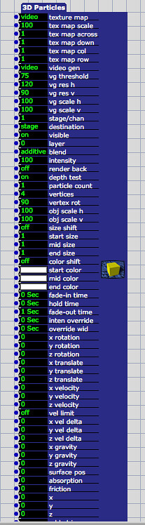
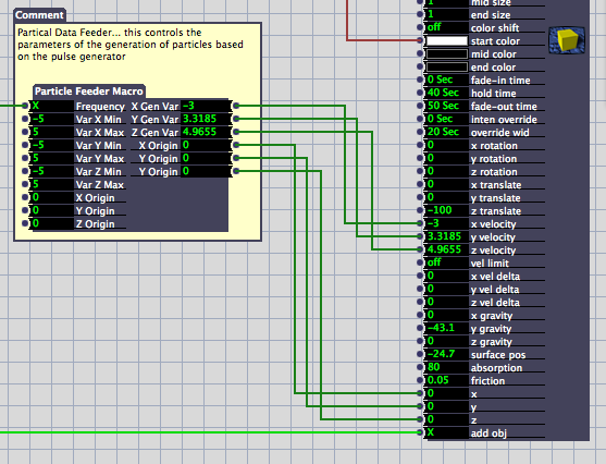
In just a moment we'll take a look inside of this user actor, but before we dive inside let's examine how we're feeding the particle generator some information. Frequency is the input for the pulse generator, this is how quickly we're generating particles. Var X, Y, and Z are used to generate a random range of velocities for our particles between an upper and lower limit. This makes sure that our particles aren't uniform in how they're moving in the space. If we don't have any variation here our particles will all behave the same way. Finally we have a location for our emitter's location: Origin X, Y, and Z. It's important to remember that the particle system exists in 3D space, so we need three attributes to define it's location. On the right side of the actor we can see that we're passing out random values between our min and max values for X, Y, and Z as well as a X, Y, and Z origin data. 

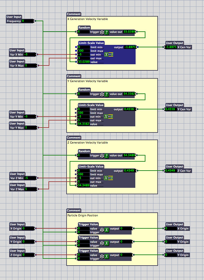
Inside of this custom actor we see this:


At first glance we can see that we have four blocks of interest for this actor. First off it's important to notice that our Frequency input is passed to all of our modules. The first three modules are copies of one another (one for X, Y, and Z). We can see here that our pulse generator is banging on a random number generation actor, that random value (from 0 to 100) is then passed to a Limit-Scale Value actor. The limit scale actor takes an input value in a specified range and scales it to another range. In our case it's taking values between 0 and 100 and scaling them to be between -5 and 5. The resulting value is then passed out of this macro to it's corresponding value.  Our bottom block pushing out data about our emitter location. It's important to remember that we need to pass out the origin location for each particle that's generated. This is why the location information is passed through a trigger value that's being triggered by our systems pulse generator.

If we jump back out of our user actor can see how our input parameters are then passed to the 3D particle actor:


Ultimately, you'll need to do your own experimenting with particle systems in order to get a firm handle on how they work. I found it useful to use custom actors to tidy up the patch and make sense of what was actually happening. I think the best way to work with particles is to get something up and running, and then to start by changing single attributes to see what kind of impact your change is making. If you're not seeing any changes you may try passing your value through a trigger that's attached to your pulse generator - remember that some attributes need to be passed to each particle that's generated. 

Are some of these pictures too small to read? You can see larger versions on flickr by looking in this album: Grad School Documentation


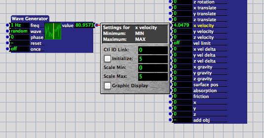
One of the great joys of sharing your work is the opportunity to learn from others. John Collingswood (for more about John check out dbini industries and Taikabox), pointed out on Facebook that one of the very handy things you can do in isadora is to constrain values by setting the range of an input parameter. For example, I could forgo the min-max system set-up with my user actor and instead scale and constrain random values in the 3D particle input. When you click on the name of an input on an actor your get a small pop-up window which allows you to specify parameters for that input's range and starting values. This means that you could connect a wave generator (with the wave pattern set to random) to an input on a 3D particle actor and then control the range of scaled values with the 3D particle actor. That would look something like this:


Monday, April 22, 2013

TouchDesigner | The Underlying Geometry

One of the benefits of working with TouchDesigner is the ability to work in 3D. 3D objects are in the family of operators called SOPs - Surface Operators. One of the aesthetic directions that I wanted to explore was the feeling of looking into a long box. The world inside of this box would be characterized by examining artifacts as either particles or waves with a vaguely dual-slit kind of suggestion. With that as a starting point I headed into making the container for these worlds of particles and waves.


Before making any 3D content it's important to know how TouchDesigner processes these objects in order to display them. On their own, Surface Operators can't be displayed as a rendered texture. In TouchDesigner's idiom textures are two-dimension surfaces, and it follows that the objects that live in that category are called TOPs, Texture Operators. Operators from different families can't be directly connected with patch chords. In order to pass the information from a SOP to a TOP one must use a TOP called a Render. The Render TOP must be connected to three COMPs (Compositions) in order to create an image that can be displayed. The render TOP requires a Geometry COMP (something to be rendered), a Light COMP (something to illuminate the scene), and a Camera COMP (the perspective from which the object is to rendered). In this respect TD pulls from conventions familiar to anyone who has worked with Adobe's After Effects. 

Knowing the component pieces required in order to successfully render a 3D object it's easier to understand how I started to create the underlying geometry. The Geometry COMP is essentially a container object (with some special attributes) that holds the SOPs responsible for passing a surface to the Render TOP. The default Geometry COMP contains a torus as a geometry. 


We can learn a little about how the COMP is working by taking a look inside of the Geometry object. 


Here the things to pay close attention to are the two flags on the torus object. You'll notice in the bottom right corner there is a purple and a blue circle that are illuminated. The purple circle is a "Render Flag" and tells TouchDesigner to render the object, and the blue circle is a "Display Flag" which tells TouchDesigner that this is the object that should be displayed in the Geometry COMP.

Let's take a look at the network that I created.


Now let's dissect how my geometry network is actually working. At first glance we can see that multiple objects are being combined into a single piece of geometry that's ultimately being passed out of this Geometry COMP. 


If we look closer we'll see that here that the SOP network looks like this:
Grid - Noise - Transform - Alpha Noise (here the bypass flag is turned on)
Grid creates a plane that's created out of polygons. This is different from a rectangle that's only composed four points. In order to create a surface that can deform I needed a SOP points in the middle of it. The grid is attached to a Noise SOP that's animating the surface. Noise is attached to a transform SOP that allows me to change the position of this individual plane. The last stop in this chain is another Noise SOP. Originally I was experimenting with varying the transparency of the surface. Ultimately, I decided to move away from this look. Rather than cutting this out of the chain, I simply turned on the Bypass Flag which turns off this single SOP. This whole chain is repeated eight times (for a total of eight grids). 


These Nine planes are then connected so that the rest of the network looks like this:
Merge - Transform - Facet - Texture - Null - Out
Merge takes all of the inputs and puts them together into a single piece of geometry. Transform allows me to move object as a whole in space. Facet is a handy operator that allows you to compute the normals' of a geometry, which is useful for creating some more dynamic shading. Texture was useful for another direction that I was exploring, ultimately  ended up turning on the bypass flag for this SOP. A null, like in other environments, is really just a place holder kind of object. In the idiomatic structure of TouchDesigner, the Null is operationally an object that one places at the end of operation string. This is considered a best practice for a number of reasons. High on the list of reasons to end a string in a Null is because this allows easy access for making changes to a string. TouchDesigner allows the programmer to insert operations between objects. By always ending a string in a Null it becomes very easy to make changes to the stream without having to worry about re-exporting parameters. Finally all of this ends in an Out. While the Out isn't necessary for this string, at one point I wasn't sure if I was going to pass this geometry into another component. Ending in the Out ensured that I would have that flexibility if I needed it.

Sunday, April 21, 2013

TouchDesigner | Time Trigger

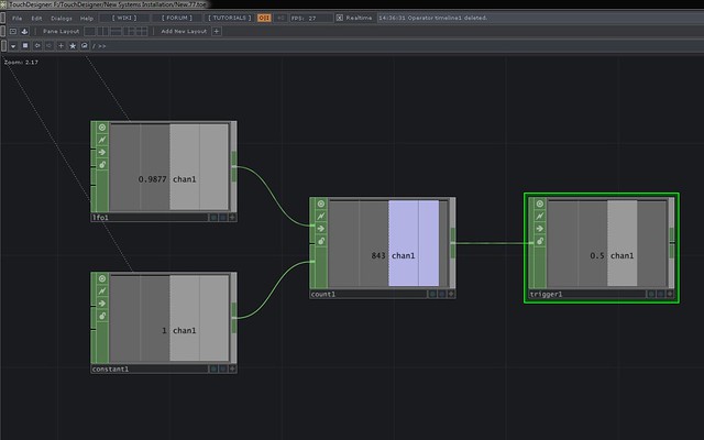
Ultimately I don't know how practical this method is, but at the moment it feels like a victory. Creating a time based trigger in TouchDesigner can be accomplished a ton of ways, the method I'm using uses the following CHOPS: LFO, Constant, Count, Trigger. 

The set to the same sample rate as the project will cross 0 once per second. The constant indicates the rate at which you wish to count. Count will use the input from the LFO and the Constant to count at the rate specified by the constant every time the LFO crosses 0. This is attached to a trigger CHOP. The trigger's threshold can e set to to the time (in seconds) appropriate for the transition. Bang. A time based triggering method using four CHOPs.


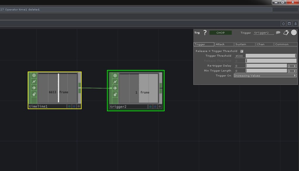
It's also worth nothing that another method for achieving this same  triggering method would be to use just two CHOPs: Timeline and Trigger. The Timeline chop will report out the current position as a frame number. Provided that you know the time (and therefore frame number) you can use this to set the threshold for a trigger value.


Sunday, April 14, 2013

Hardware and Software | Bootcamp Woes


Rough. This whole business is rough.

Curse you Touch Designer, and your allure.

One of the many pieces of software that's caught my eye over the last year has been Derivative's Touch Designer. TD is built around the idea of visual thinking, and is made to run rich visual experiences. It's built to be hardware accelerated in nearly every aspect, and exists somewhere in the space between Isadora, Max MSP, and Quartz Composer. As a nodal based programming environment, it also works within the idiomatic framework of a timeline based system. It might not be the best tool for media designers (at least as we're being trained right now), but it's a glimpse of the future in terms of a tool that's built with the intention for programmer / designers to dream big enough and make just about anything.

Right now TD is a windows only application. For me that means buying a windows based computer / laptop or getting with the program and creating a second partition for Windows on my Macbook Pro. 

My first bout with this idea was rough going. 

I might be a Mac user, but I'm also a frugal Mac user. When I purchased a laptop at the start of the academic year I knew that I was ultimately going to use OWC's Data Doubler to install another hard drive in the traditional 15" body of my 2013 Macbook Pro. I purchased a SSD for applications, and the OS to run off of and did the dance of opening up the case of a fairly new MB Pro. This is far from my first foray into hardware customization, but it was a little daunting given how tightly packed Apple makes its computers. Nerves aside, after watching plenty of tutorials, and making back up copies of my data I worked through the process without too many hiccups. I ended up moving the platter based drive to the optical bay, and placing the SSD in the traditional Hard Drive slot. 

I did all of this about 4 months ago, and it was after this that I decided to get a windows partition up and running. I'm a jealous man when it comes to my SSD space, and consequently I decided that I wanted to install the Windows partition on my platter drive. This proved to be easier said than done. Apple advises users against using Bootcamp to instal windows to anything but the drive in the main slot. Their advice is to remove other drives, install to the destination drive, and then reinstall the other drives. Sound advice that I didn't initially follow. After backing up all of my data I started by trying to install to my second drive out the gate. I didn't manage to get very far here, so I ended up opening the case on the MBP and removing the SSD. Now I was able to get one step further into the Windows installation process, but quickly got stuck again. Windows uses a MBR structure on its boot drives, and OSX uses a GUID table. Part of what Bootcamp does is to do some software magic so that your partitions will play nicely with one another. My platter drive was still set up as GUID, and the windows installer was unable to reformat the drive by itself. I reinstalled the SSD, reformatted the platter drive as NTFS, removed the SSD, and got back to work. This time I was able to make it all the way through the install process. I reinstalled the SSD with the OSX volume, but was unable to boot into anything but windows. No amount of the option key when restarting or using the windows Bootcamp assistant would solve this problem. Finally I had to open the case again, pull out the platter drive, reformat it with another computer, reinstall it, and then I was back in business - albeit with only the OSX volume. 

Feeling gun shy I decided that I wouldn't bother with a windows partition.

Then I started working with TD more and more on a loaned computer. 

So I changed my mind. This time, however, I decided that I would be willing to share my SSD with the windows partition. I made a plan, and set aside some afternoon to get this done. I backed up all of my data and wanted to get to work. Start things process I soon found out that my first trip down Bootcamp lane had left me with a mystery partition that I couldn't delete, and that was blocking the install process. With everything backed up I decided that I would just reformat, do a clean install of Mountain Lion, and start there. With a copy of OSX installed on USB key I went to work, and while I could still boot into my user account, from the USB boot I wasn't able to reformat the drive. Okay, no problem I decided to pull out the drive and reformat it on another computer, start with a blank drive, and install OSX. 

No dice. 
In trying this, I couldn't manage to boot from the USB key at all. 

No dice.
Next up I tried another USB key. 

No dice. 
So I pulled the drive from the computer, then installed a clean image on the drive. I went to restart my MBP with the restored image. 

No dice. 
I connected one computer to another and started the troubled mac in Target disk mode. Here I was able to see the drives in question, and do some adjusting. 

Restart, still no dice. Started in restore mode, and I can't see the SSD anymore. I formatted the old HDD, and installed Mountain Lion. Once Mountain was installed, I was finally able to see the SSD. From here on in the trouble shooting got easier. I reformatted the SSD, cloned the working OS instal over to to the freshly formatted drive, then restored data and settings from a Time Machine backup. From here I followed along with the Bootcamp installation guide. The one hiccup here was that I still had a USB drive attached when I was working through the install process. Using the back arrow to rewind to the beginning of the Windows 7 install process and removing the USB attached drive got me where I needed to go. Finally I had a Windows 7 partition and an OSX volume up and running. 

Touch Down.

From here on in the rest of the process was just about details. I split the larger platter HHD into two partions - one HFS and one NTFS. While the windows partition can see all of the data on my HFS drives, I can't write to them. I'll use the NTFS formatted drive as works space and storage space for the TD work that I'll do. 

I hit a lot of walls in this process, but have learned a lot as well. If nothing else, persistence really is the name of the game some times. I'm also fortunate to have started this process over a weekend this time around instead of late at night. All of the trouble spots I planned for weren't trouble spots at all, it was the things I didn't plan for that ended up being issues. "Life is what happens when you're busy making plans," and in the same way, the hurtles that this kind of work throws my way are often the things I least expected. I don't know that I'm in any hurry to do this whole process again, but it is nice to know that I'm up for the challenge.

Helpful Links During this process:
Getting a "device in use" error when trying to restore an image try this
The Mac Start-Up Manager