Showing posts with label Isadora. Show all posts

Monday, May 20, 2013

Isadora | Button Basics


In a previous post I talked about how to get started in Isadora with some basics about slider operation. I also want to cover a little bit about using buttons with Izzy. 

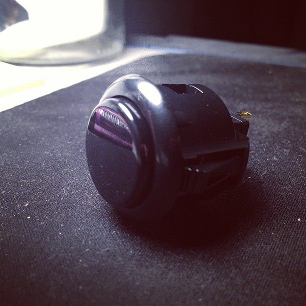
Buttons are very handy interface controls. Before we get started, it’s important to cover a few considerations about how buttons work. When working with a physical button, like an arcade button on a midi controller, the action of pressing the button completes a circuit. When you release the button, you also break the circuit. In Isadora, we can control what happens when we press a button. Specifically, we can control what values are being transmitted when the button isn’t being pressed, when it is being pressed, and how the behaves (does it toggle, or is the signal momentary). Thinking about how a button behaves will help as you start to build an interface, simple or complex.

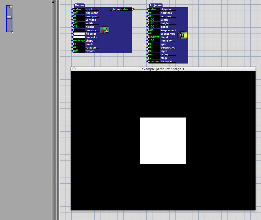
Let’s start by experimenting with a simple implementation of this process. We’ll create a white rectangle that fills our stage, connect our shape to a projector, and finally use a button to control the intensity of the projector. 

Start by creating a new scene, and adding a “Shapes” actor and a “Projector” actor. Connect the shapes’ video outlet to the projector’s video inlet.
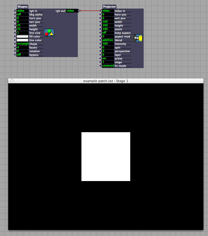


Next change the width and height dimensions of the shape to be 100 and 100 respectively. Remember that Isadora doesn’t use pixel values, but instead works in terms percentage. In this case a value of 100 for the hight indicates that the shape should be 100% of the stage’s height, the same applies for the width value of 100. 


We should now have a white box that covers the height and width of the stage so that we only see white. 

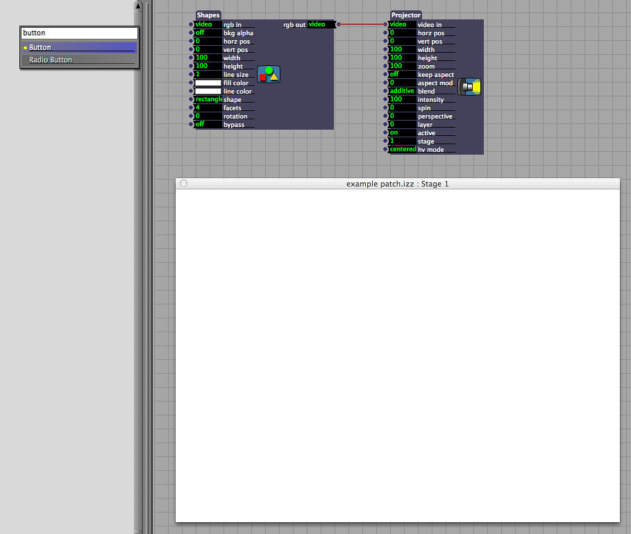
Now we’ll use a button to control a change in the stage from white to black. Remember that in order to start adding control elements we first need to reveal the control panel. You can do this by: selecting it from the drop down menu use Command-Shift-C to see only the control panel or use Control-Shift-S to see a split of the control panel and the programming space. If you've turned on the Grid for your programming space you'll be able to see a distinct difference between the control panel space (on the left) and the programming space (on the right). You'll also notice that with your Control panel active your actor selection bins have been replaced by control panel operators.

With the control panel visible, add a button. 


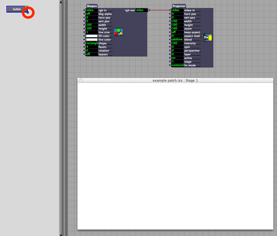
Once you’ve added your button to the control panel, you can change the size of the button by clicking and dragging the small white square on the bottom right of the button. 


Next let’s look at the options for the button. We can see what parameters we can control by double clicking on the button. When you do this you should see a pop up window the the following attributes:

  • Control Title - what the control is named
  • Width - how wide is this control (in pixels)
  • Height - how tall is this control (in pixels)
  • Font - the font used for this control
  • Font Size - self explanitory
  • Show Value of Linked Properties - this allows data from the patch itself to feed back into the control panel
  • Button Text - the text displayed on the button
  • Control ID - the numerical identification number of this contorl
  • Off Value - the numeric value sent when the button is in the off position
  • On Value - the numeric value sent when the button is in the on position
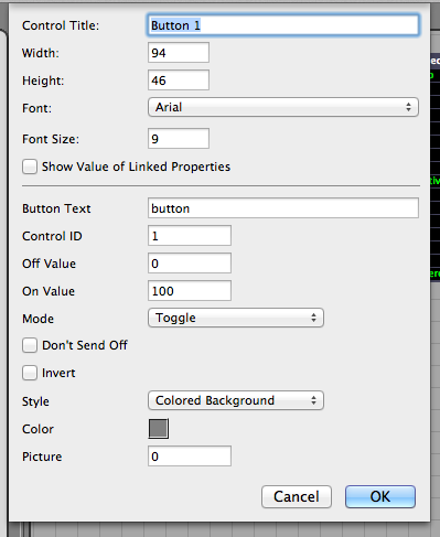
  • Mode (Momentary or Toggle) - the mode for the button. Momentary indicates that the on value is only transmitted while the button is being pressed. Toggle indicates that the values with toggle between on and off values with a click.
  • Don’t Send Off - prevents the button from sending the off value
  • Invert - inverts the on and off values
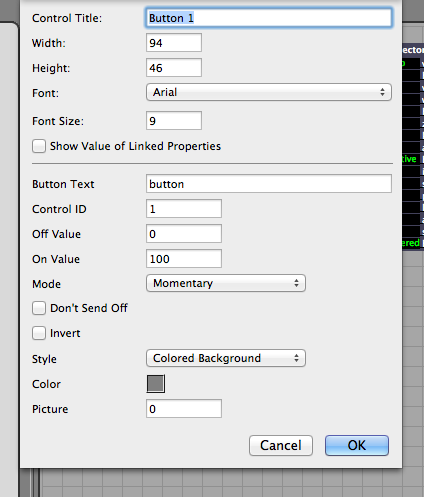


There are a few other options here, but they mostly have to deal with the appearance of the button. When you start thinking about how you want your control panel to look to an operator, these last parameters will be very helpful. 

For right now let’s leave the default parameters for the button’s options. Next connect the button’s control ID to the inlet on the Projector labeled “intensity.”


As we’re working on the control panel our edit mode is currently enabled which will prevent us from being able to actually click the button with the mouse. To check the controls we have two options:

We can disable edit mode by right clicking on the control panel work space and selecting “Disable Edit Mode” from the contextual menu. 
We can use the option key to by-pass the above process. 
If you’re doing some extensive testing of your control panel I’d recommend that you disable edit mode. On the other hand, if you’re only testing a single slider or button, I’d recommend using the option key as a much more efficient alternative.  

Holding down the option key, you should now be able to click the button in the control panel. You should see the white box flash on, and back off again as you press and release the mouse button. Right now as we click the button we’re sending a value of 100 to the intensity parameter of the Projector actor. This makes the shape opaque only so long as you’re pressing the button. 

Double click the button in the control panel and check the box for “Invert.” We’ve now inverted the message being sent from the bottom to the Projector. When you click the button you should now see the opposite. A white screen that flashes black, and then returns to white. 


Double click on the button in the control panel, uncheck the box for “Invert.” Change the “Mode” of the button from “Momentary” to “Toggle.” Now as you click the button you should notice that it stays depressed until you click it again. This allows you to toggle between the on and off states of the button. 


This, obviously, is only the beginning of how to work with Buttons. You might use a button to control the play back of a movie, what media was on the stage, the position of media on a stage, to jump between scenes, or to change any number of parameters in you parch. Knowing the basics of how buttons behave will help ensure that you can start to build a solid control panel that you can use during a live performance. 


Friday, May 17, 2013

Isadora | Slider Basics

One of the most exciting (and also most challenging) parts of working with Isadora is thinking about how an operator is going to use your patch during a show. ASU's program focuses on the importance of programming a show with the expectation that the person running your system may, or may not, have much experience. During the tech rehearsal process one of the Media Designer's responsibilities is to train the operator with basic operation and trouble shooting techniques. 

While there are a wide variety of methods for controlling your system I want to take a moment to cover how you can use the Control Panel features of Isadora to create a simple custom interface. I'm also going to take a moment to talk about the different kinds of controls, how they work, and things you want to keep in mind as you're using them. 

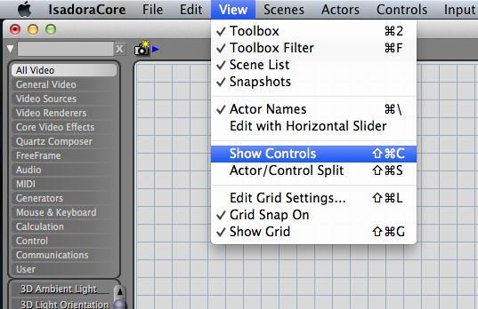
To get started, there are few different ways to reveal the control panel. You can:  select it from the drop down menu use Command-Shift-C to see only the control panel or use Control-Shift-S to see a split of the control panel and the programming space. If you've turned on the Grid for your programming space you'll be able to see a distinct difference between the control panel space (on the left) and the programming space (on the right). You'll also notice that with your Control panel active your actor selection bins have been replaced by control panel operators.

As you create new scenes, Isadora will start by connecting all scenes to the same control panel. There are a few different schools of thoughts in terms of best practice in the use of control panels. Using a single control panel for every scene means only building a single interface. As long as you’re only dealing with a limited number of simple cues this is a fine direction to head, and may be the easiest method in terms of programming. This approach can, however, get complicated very quickly if you’re triggering more than one actor per scene. In this scenario the programmer could loose track of where a button or slider is connected. This might cause unexpected playback results or could just be a source of headaches. For more complicated play-back situations, you may instead elect to have separate control panels for each scene. Depending on your programming needs this may be the best way to ensure that your controls are only linked to a single scene. 


To accomplish this, you’ll need to split your control panel. Isadora gives you several visual cues to determine how a scene and control panel are linked. When you glance at your scene list you’ll notice that the bar underneath is either continuous (a single control panel) or broken (a split control panel). 


To split the control panel click between the two scenes that you wish you separate. When you see your cursor separating the two scenes right click to get a contextual menu with the option to split the control panel. You should now see that the line between the two scenes is now broken. 


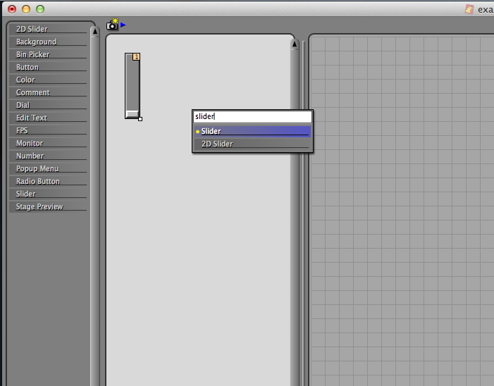
Let's start by looking at a simple slider. To add a slider to your control panel start by double clicking in the control panel work space. Next type in “slider” and select it when it appears in the drop down menu. 


It’s important to note that there is a difference between the 2D slider, and the regular slider. For now, we just want the “slider” control. We can learn a little more about what our slider is doing by double clicking on it. 


You should see a pop up window with lots of information about our slider:
  • Control Title - what this control is named
  • Width - how wide is this control (in pixels)
  • Height - how tall is this control (in pixels)
  • Font - what’s the font used for this control
  • Font Size - self explanatory
  • Show Value of Linked Properties - this allows data from the patch itself to feed back into the control panel. As a note, for this to work properly, you’ll also need to enable the “Display Value” check-box (a big thank you to Matthew Haber for catching my error here)
  • Control ID - the numerical identification number of this control
  • Minimum - Slider’s work on a principal that at the bottom, or left, position this control switch will send the number that’s indicated in this box.
  • Maximum - Slider’s work on a principal that at the top, or right, position this control switch will send the number that’s indicated in this box.
  • Step - The counting increments for this control.
  • Display Value - Shows the current value being sent in the control panel itself.
  • Display Format - The number of floating points displayed.
  • Color - The color of the inside of the slider.
There are a few other options here, but they’re largely aesthetic, so I’m going to skip them for now.

Let’s start by working with the default values for the slider and to see how this is communicating with the patch itself. 

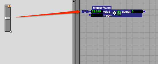
First, we will add a trigger value to the programming space so we can see how values are transferred from the control panel to the programming environment.


Next we can connect the Control ID from the control panel to the Value inlet not he Trigger Value Actor. We can do this by clicking on the Control ID, and dragging the red line to the “value” input.


You should now see a number next to the value input that corresponds to the slider’s control ID.


As we’re working on the control panel our edit mode is currently enabled which will prevent us from being able to actually move the slider with the mouse. To check the controls we have two options:
  • We can disable edit mode by right clicking on the control panel work space and selecting “Disable Edit Mode” from the contextual menu. 
  • We can use the option key to by-pass the above process. 
If you’re doing some extensive testing of your control panel I’d recommend that you disable edit mode. On the other hand, if you’re only testing a single slider or button, I’d recommend using the option key as a much more efficient alternative.  

Holding down the option key, you should now be able to move the slider in the control panel. You’ll notice that the value linked to the slider also changes.


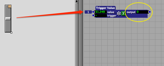
You’ll also notice that the output from the trigger value has not changed. This is because we’re only adjusting the value, but not activating the trigger. Let’s activate the trigger at the same time we’re moving the slider.


To do this we attach the Control ID to the trigger inlet on the Trigger Value Actor. This will ensure that the actor triggers at the same time that the value is changed. Now when we move the the slider we can see that the output value also changes.


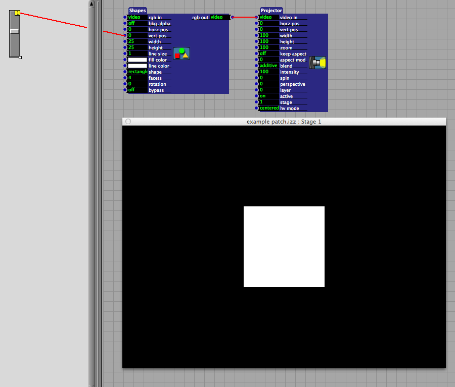
Now that we know how to send slider data to a trigger value we can now look at something a little more interesting. We are going to start by adding a shape actor and connecting that to a projector actor.


Next connect your vertical slider to the “vert pos” (Vertical Position) inlet on the shapes actor. 


Create a new slider in the control panel. Grab the small box on the bottom right corner and drag the slider to the right until you have created a horizontal slider. 


Connect your horizontal slider to the “hora pos” (Horizontal Position) inlet on the shapes actor.


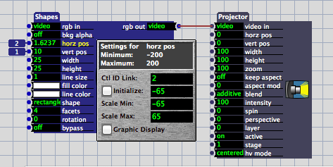
Next we need to adjust the scaling values of the shape actor. Actor’s inlets and outlets can often be scaled to a set range. In order to properly use our slider we’ll need to adjust the inlet scaled values on the Shapes Actor. To do this click on the name of the attribute whose scaled values you’d like to adjust. Start by clicking on “hora pos.” We can see in the pop-up menu that the minimum value is currently set to −200, and the maximum value is set to 200. These values are too high. 


Isadora uses a coordinate system that assumes that the middle of the stage is the origin 0,0. Further, Isadora thinks in terms of percentages rather than pixels. In the case of our horizontal slider, a positive value of 50 represents half of the total stage length which puts us at the right most edge of the stage. In the case of shapes it’s also important to note that the shape’s position is relative to it’s center. A positive value of 50 still leaves half of our shape on the screen, no matter the dimensions of the shape.

Set the scaled values of the horizontal position to −65 and 65. Now when we drag our slider (remember to hold down the option key) we are able to move our box from all the way off the stage on the left to all the way off the stage on the right.


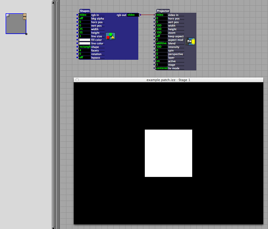
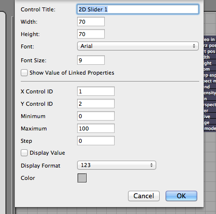
Another type of slider that might be self in this type of situation is the 2D slider. Create a new scene and split the control panel so we can see how this input control works. In the new scene add a Shapes Actor and a Projector Actor, and connect them. Now open add a 2D slider to the control panel.


Double click on the 2D slider so you can see a little more about how this particular control input works. Similar to the “slider” control you can see that you can title the slider, adjust the width, height, font, and so on. You’ll notice that there’s a X Control ID and a Y Control ID. 


Next we’ll click okay, and link Control ID 1 (the X control) to the “horz pos” inlet on the Shapes Actor. Now link the Control ID 2 (the Y control) to the “vert pos” inlet on the Shapes Actor. Check to make sure that the horizontal and vertical inlets on the Shapes Actor are properly scaled (last time we set them to −65 and 65).


Now the single 2D slider behaves in the same way as the two sliders we set-up in the exercise above.

This, obviously, is only the beginning of how to work with Sliders and 2D Sliders. You might use a slider to control the playback position of a movie, or the position of a movie on the stage. You might use a slider to control position, zoom, rotation, width, height, really just about any kind of numerical attribute for an actor. The key things to keep in mind in this process are:
  • Knowing the range of values that your slider is transmitting
  • Knowing the scaled range of values that your actor is transposing values to
  • Knowing control ID
  • Knowing how to connect your control panel items to Actors in your patch


Sunday, April 28, 2013

Isadora | Network Control

For an upcoming show one of the many problems that I'll need to solve is how to work with multiple machines and multiple operating systems over a network. My current plan for addressing the needs of this production will be to use one machine to drive the interactive media, and then to slave two computers for cued media playback. This will allow me to distribute the media playback over several machines while driving the whole system from a single machine. My current plan is to use one Mac Pro to work with live data while slaving two Windows' 7 PCs for traditionally cued media playback. The Mac Pro will drive a Barco, while the PC's each drive a Sanyo projector each. This should give me the best of both worlds in some respects. Distributed playback, similar to WatchOut's approach to media playback, while also allowing for more complex visual manipulation of live-captured video. 

To make all of this work, however, it's important to address how to get two different machines running Isadora on two different operating systems to talk with one another. To accomplish this I'm going to use an OSC Transmit actor on the Master machine, and an OSC listener on the slaved machines. 

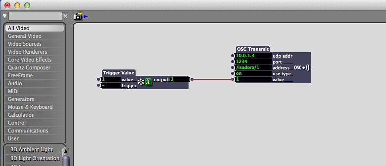
On the Master machine the set-up looks like this:
Trigger Value - OSC Transmit
The transmit actor needs the IP address of the slaved machines, as well as a port to broadcast to. The setup below is for talking to just one other machine. In my final setup I'll create a specialized user actor that holds two OSC Transmit actors (one for each machine) that can be copied into each scene.


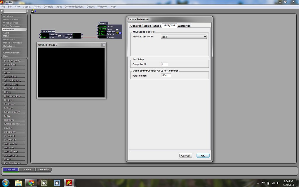
On the Slaved machines the setup takes two additional steps. First off it's important to determine what port you want to receive messages from. You can do that by going to Isadora Preferences and selecting the Midi/Net tab. Here you can specify what port you want Isadora to listen to. At this point it's important to catch the data stream. You can do this by oping up the Communications tab and selecting Stream Setup. From here make sure that you select "Open Sound Control" and click the box "Auto-Detect Input." At this point you should see the Master Machine broadcasting with a channel name an address, and a data stream. Once this is setup the Actor patch for receive messages over the network looks like this:
OSC Listener - Whatever Actor you Want
In my case I'll largely use just jump++ actors to transition between scenes, each with their own movie. 


You can, of course, do much more complicated things with this set-up all depending on your programming or play-back needs. 

Isadora | Live-Camera Input as a Mask


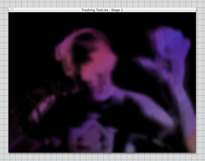
Back in March I had an opportunity to see a production called Kindur put on by the Italian Company Compagnia TPO. One of the most beautiful and compelling effects that they utilized during the show was to use a live-camera to create a mask that revealed a hidden color field. The technique of using a live feed in this way allows a programmer to work with smaller resolution input video while still achieving a very fluid and beautiful effect. 

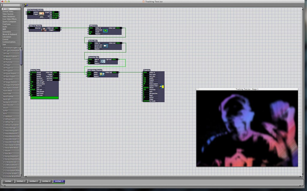
This effect is relatively easy to generate by using just a few actors. An overview of the whole Isadora Scene looks like this:


To star this process we'll start with a Video-In Watcher actor. The video-in will be the live feed from our camera, and will ultimately be the mask that we're using to obscure and reveal our underlying layer of imagery. This video-in actor connects to a Difference actor which looks for the difference between two sequencial frames in the video stream. This is then in turn passed to a Motion Blur actor. The motion blur actor will allow you to specify the amount of accumulated blur effect as well as the decay (disappearance rate) of the effect. To soften the edges of this the image stream is next passed to a Gaussian Blur actor. Finally this stream is passed to an Add Alpha Channel actor by passing the live feed into the mask inlet on the actor. The underlying geometry is then passed in through the video inlet in the Add Alpha Channel actor. Finally, the outlet of the Add Alpha actor is passed out to a projector. 


As a matter of best-practice I like to use a Performance Monitor actor when I'm creating a scene in order to keep an eye on the FPS count. This can also be useful when trying to diagnose what's causing a system to slow down during playback. 

This effect works equally well over still images or video, and is certainly something that's fun to experiment with. Like all things in live systems, your milage may vary - motion blur and gaussian blur can quickly become resource expensive, and it's worth turning down your capture settings to help combat a system slow-down.

Wednesday, April 24, 2013

Soot and Spit | Particles in Isadora

Holy challenges Batman. It seems like I'm constantly being humbled by the learning curve of graduate school. This spring one of ASU's productions is Charles Mee's Soot and Spit. 


Soot and Spit is grounded in the work of James Castle, an artist who was deaf and possibly autistic. One of the most powerful outlets for expression in Castle's life was making art. He made countless works over the course of his life, and one of the mediums that he used was a mixture of soot and spit. With this as a contextual anchor the lead designer, Boyd Branch, was interested in exploring the possibility of using particles as a part of his final design. 

One of my charges in working on this production was to explore how to work with particles in Isadora (our planned play-back system). I started this process by doing a little digging on the web for examples, and the most useful resource that I found as a starting point was the Mark Coniglio (Isadora's creator) example file. Here Mark has a very helpful breakdown of several different kinds of typical operations in Isadora, including a particle system. Looking at the Particle System Actor can feel a little daunting. In my case, The typical approach of toggling and noodling with values to look for changes wasn't really producing any valuable results. It wasn't until I took a close look at Mark's example patch that I was able to finally make some head way.

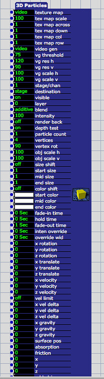
We can start by looking at the 3D particle actor and working through a few important considerations to keep in mind when working with 3D particles in Isadora. One thing to remember is that when you're creating particles, the rendering system needs multiple attributes for each particle that you're generating (location in x, y, and z, velocity, scale, rotation, orientation, color, lifespan, and so on). To borrow a idiomatic convention from MaxMSP, you have to bang on these attributes for every particle that you create. There are a variety of methods for generating your bang, but for the sake of seeing some consistent particle generation I started by using a pulse generator. Pulse generators in Isadora are expressed in hertz (cycles per second), and when we're working with our particle system we'll frequently want a pulse generator to be attached at the front end of our triggers. To that end, we really want a single pulse generator to be driving as much of our particle generation as possible. This is to ensure all of our data about particle generation is synchronized, and to keep our system over head as low as possible. 

Let's get this party started by making some conceptual plans about how we want to experiment with particles. I started by thinking of the particles as being emitted from a single source and being affected by gravity in a typical manner, i.e. falling towards the ground. 

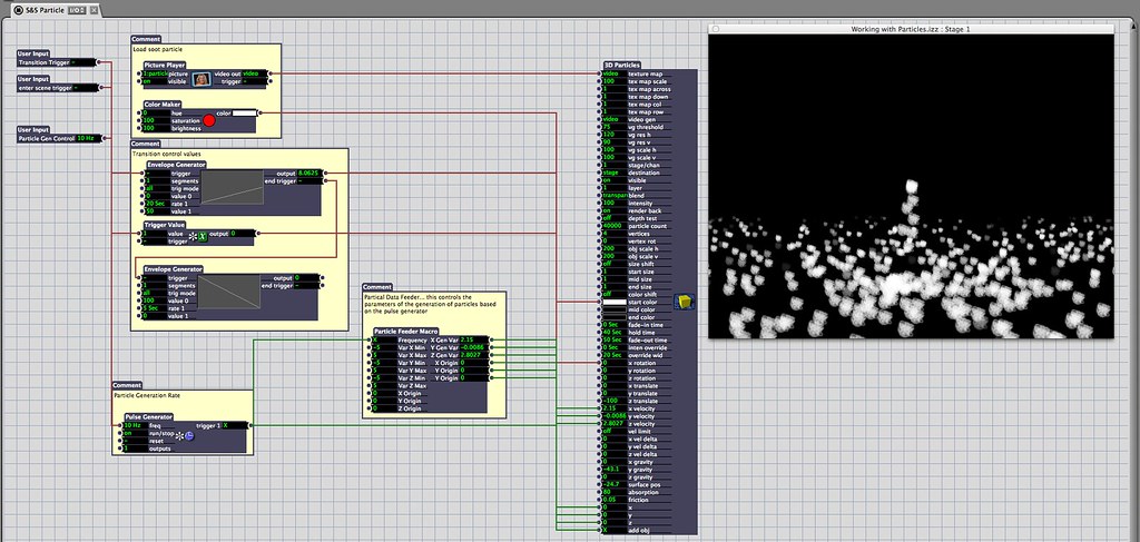
Here's my basic particle emitter set-up for this kind of setup:


Let's start by taking a look at the things we need to get started. As I mentioned before we need to start by frist getting a pulse generator set-up. Let's start by adding a pulse generator, and looking at where it's connected:


Here we can see that the pulse generator is hooked up to a custom user actor that I've called "Particle Feeder," and to the "Add Obj" attribute in the 3D particle Actor. This approach is making sure that we're only using a single pulse generator to bang on our particle system - pushing attribute changes and add object changes.

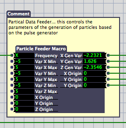
Next let's look at the Particle Feeder actor that I made to make this process easier:


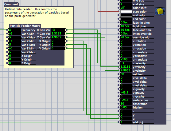
In just a moment we'll take a look inside of this user actor, but before we dive inside let's examine how we're feeding the particle generator some information. Frequency is the input for the pulse generator, this is how quickly we're generating particles. Var X, Y, and Z are used to generate a random range of velocities for our particles between an upper and lower limit. This makes sure that our particles aren't uniform in how they're moving in the space. If we don't have any variation here our particles will all behave the same way. Finally we have a location for our emitter's location: Origin X, Y, and Z. It's important to remember that the particle system exists in 3D space, so we need three attributes to define it's location. On the right side of the actor we can see that we're passing out random values between our min and max values for X, Y, and Z as well as a X, Y, and Z origin data. 

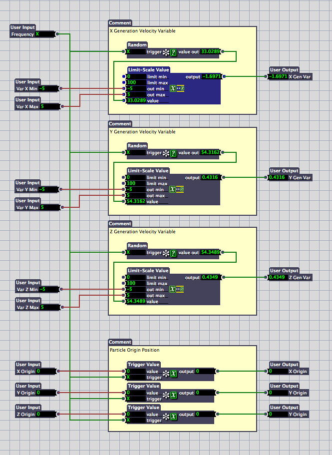
Inside of this custom actor we see this:


At first glance we can see that we have four blocks of interest for this actor. First off it's important to notice that our Frequency input is passed to all of our modules. The first three modules are copies of one another (one for X, Y, and Z). We can see here that our pulse generator is banging on a random number generation actor, that random value (from 0 to 100) is then passed to a Limit-Scale Value actor. The limit scale actor takes an input value in a specified range and scales it to another range. In our case it's taking values between 0 and 100 and scaling them to be between -5 and 5. The resulting value is then passed out of this macro to it's corresponding value.  Our bottom block pushing out data about our emitter location. It's important to remember that we need to pass out the origin location for each particle that's generated. This is why the location information is passed through a trigger value that's being triggered by our systems pulse generator.

If we jump back out of our user actor can see how our input parameters are then passed to the 3D particle actor:


Ultimately, you'll need to do your own experimenting with particle systems in order to get a firm handle on how they work. I found it useful to use custom actors to tidy up the patch and make sense of what was actually happening. I think the best way to work with particles is to get something up and running, and then to start by changing single attributes to see what kind of impact your change is making. If you're not seeing any changes you may try passing your value through a trigger that's attached to your pulse generator - remember that some attributes need to be passed to each particle that's generated. 

Are some of these pictures too small to read? You can see larger versions on flickr by looking in this album: Grad School Documentation. 


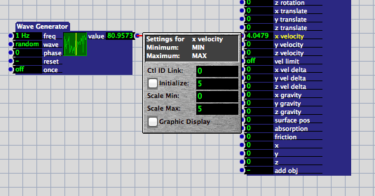
One of the great joys of sharing your work is the opportunity to learn from others. John Collingswood (for more about John check out dbini industries and Taikabox), pointed out on Facebook that one of the very handy things you can do in isadora is to constrain values by setting the range of an input parameter. For example, I could forgo the min-max system set-up with my user actor and instead scale and constrain random values in the 3D particle input. When you click on the name of an input on an actor your get a small pop-up window which allows you to specify parameters for that input's range and starting values. This means that you could connect a wave generator (with the wave pattern set to random) to an input on a 3D particle actor and then control the range of scaled values with the 3D particle actor. That would look something like this:


Tuesday, March 19, 2013

Phase 2 | Halfway House


Media design is an interesting beast in the theatre. Designers are called upon to create digital scenery, interactive installations, abstract imagery, immersive environments, ghost like apparitions, and a whole litany of other illusions or optical candy. The media designer is part system engineer, part installation specialist, and part content creator. This kind of design straddles a very unique part of the theatrical experience as it sits somewhere between the concrete and the ephemeral. We're often asked to create site specific work that relates to the geometry and architecture of the play, and at the same time challenged to explore what can be expressed through sound and light. 


One of the compelling components of ASU's School of Theatre and Film (SoTF) is its commitment to staging new works. In addition to producing works that are tried and true, ASU also encourages its students to create works for the stage. As a part of this commitment  the department has developed a three phase program to serve the process of developing a work for full main-stage production. 
  • Phase 1 - Phase one is between a staged reading and a work-shop production of a play. This phase allows the team to focus on sorting out the nuts and bots of the piece - what is the play / work really addressing  and what are the obstacles that need to be addressed before it moves onto the next stage of production. 
  • Phase 2 - Phase two is a workshop production environment  With a small budget and a design team the production team creates a staged version of the work that operates within strict design constraints. Here the lighting plot is fixed, scenic elements are limited, and media has access to two fixed projectors focused on two fixed screens.  This phase is less about the technical aspects of the production, and more focused on getting the work up in front of an audience so that the writer and director have a chance to get some sense of what direction to move next.
  • Phase 3 - Phase 3 is a full main-stage production of a work. Here there production has a full design team, larger budget, and far fewer constraints on the implementation of the production. 
While productions can skip one of the stages, ideally they are produced in at least one phase (either one or two) before before being put up as a phase three show. 


This semester I was selected to be the media designer on call for the two original works slotted in as Phase 2 productions: Los Santos, and The Halfway House. These two new works are both written by current ASU playwrights, who are invested in receiving some critical and informative feedback bout their work. The beginning part of this process begins with production meetings where directors pitch their visions of the production and start the brainstorming / creating process with the designers. Ultimately,  Los Santos decided against using any media for their production. Halfway House, however, did decide that it wanted some media driven moments in their production. 

My role in this process was to work with the director to find the moments where media could be utilized in the production, film and edit the content, and program the playback system for the short run of the production. After reading through the play a few times I met with Laurelann Porter, the director, to talk about how media could be used for this show. Important to the design process was understanding the limitations of the production. In the case of the Phase 2 productions, the projectors and screens are fixed. This limitation is in part a function of reducing the amount of tech-time, as well as limiting the complications imposed a set and lighting when doing complex projection. Looking at the script I thought the best use of media would be to enhance some of the transition moments in the production. Several of the transitions in the show involve moments where there is action taking place "elsewhere" (this is the language used by the playwright). These moments seemed perfect for media to help illustrate. In meeting with the director we identified the major moments that would benefit from some media presence, and started brainstorming from there.

A large part of the production process is planning and organization. In the case of lighting, sound, and media designers are tasked with identifying the moments when their mediums will be used, and creating a cue sheet. Cue sheets are essentially a set of discretely identified moments that allow a stage manager to give directions about how the show runs. Media, lights, and sound all have their own board operators (actual humans), and the stage manager gives them directions about when to start or stop a given cue. Creating a cue sheet with this fact in mind helps to ensure that a designer has working understanding of how to plan the moments that are being created. My process of reading the script looked like this:
  • 1st time through - for the story and arc of the action
  • 2nd time through - identify possible moments for media
  • 3rd time through - refine the moments start to create a working cue sheet
  • 4th time through - further refinement, label cues, look for problematic moments
After talking with the director and identifying what moments were going to be mediated material, it was time to create a shooting list, and plan for how to use a single afternoon with the actors to record all of the necessary footage for the show. We had one afternoon with the actors to film the transition moments. I worked with the director to determine a shooting order (to make sure that we efficiently used the actors' time), and to identify locations and moments that needed to be captured. From here it was a matter of showing up, setting up, and recording. This transitioned smoothly to the editing process that was a matter of cutting and touching up the footage for the desired look.

The School of Theatre and Film currently have two show control systems at our disposal. Dataton's Watchout4 and Troikatronix's Isadora. Given the timing of the phase 2 productions, I knew that the Isadora machine was going to be available to me for show control. Like MaxMSP, Isadora a is a node-based visual programming environment. Importantly, Isadora is truly designed with performance in mind, and has a few features that therefore make it easier to use in a theatrical production environment. 

Typically a theatrical production requires a additional steps for media that are similar to the lighting process - lensing, and plotting for example. For the Phase two productions  the the shows use a standard lighting and media plot that doesn't change. This means that there's little additional work in terms of projector placement, focusing, masking, and the like that I have to do as a designer. For a larger production I would need to create a system diagram that outlines the placement of computers, projectors, cable, and other system requirements. Additionally, I would need to do the geometry to figure out where to place the projectors to ensure that I had a wide enough throw with my image to cover my desired surfaces, and I would need to work with the lighting designer to determine where on the lighting plot there was room for this equipment. This element of drafting, planning, and system design can easily be taken for granted by new designers but it's easily one of the most important steps in the process as has an effect on how the show looks and runs. With all of the physical components in place, and the media assets created the designer is now looks at programming the playback system. In the case of Isadora this also means designing an interface for the operator.

One of the pressing realities of designing media for a theatrical installation is the need to create playback system knowing that someone unfamiliar with the programming environment will be operating the computer driving the media. ASU's operators are typically undergraduate students that may or may not be technical theatre majors. In some cases an operator may be very familiar with a given programming interface, while others may not have ever run media for a show. Theatre in educational institutions are a wonderful place for students to have an opportunity to learn lots of new tools, and get their feet wet with a number of different technologies. In this respect I think it's incumbent upon the designer to create a patch that has an interface that's as accesible as possible for a new operator. In my case, each moment in the show where there is media playing (a cue) has  corresponding button that triggers the start, playback, and stop for the given video. 

Media is notoriously finicky in live performance. It can be difficult to program, washed out by stage lights, perform poorly if it’s not encoded properly, or any host of other possible problems. In the case of Half Way House, the process went very smoothly. The largest problem had more to do with an equipment failure that pushed back equipment installation than with the editing or programming process. While this is a simple execution of using media in a production, it was valuable for a number for the individuals involved in the process - the director, lighting designer, sound designer, and stage manager to name only a few. There are large questions in the theatre world about the role of media in production - is it just fancy set dressing? how is it actively contributing to telling the story of the show? is it worth the cost? does it have a place in an idiom largely built around the concept of live bodies? And the list goes on. I don’t think that this implementation serves to address any of those questions, but for the production team it did start the process of demystifying the work of including media in a production, and that’s not nothing.

Tools Used
Programming and Playback- Isadora | TrokaTronix
Projector - InFocus HD projector
Video Editing - Adobe After Effects , Adobe Premiere
Image Editing - Adobe Photoshop 
Filming / Documentation - iPhone 4S, Canon 7D, Zoom H4n
Editing Documentation - Adobe Premiere, Adobe After Effects